PhotoRobot Networking: передумови та конфігурація
Наступна інформація містить детальні передумови створення мережі та конфігурацію мережі для функціональної роботи PhotoRobot. Дана технічна документація спрямована на підтримку існуючих клієнтів, які або не володіють готовим обладнанням, або чий IT-відділ вимагає самостійного налаштування.
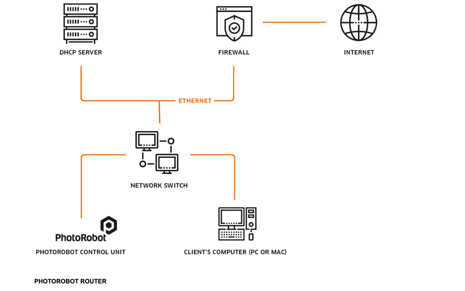
Примітка: У стандартній практиці існують попередньо налаштовані маршрутизатори, що поставляються з PhotoRobot, щоб відповідати вимогам до мережі. Це допомагає як спростити впровадження технології PhotoRobot, так і значно знизити вимоги до підтримки. У цьому випадку маршрутизатор функціонує як невелика внутрішня мережа в межах основної мережі клієнта. Ця внутрішня мережа повністю відповідає всім вимогам до зв'язку PhotoRobot. Тим часом комп'ютер, студійне освітлення (підключене через виділений Wi-Fi, щоб уникнути проблем з Wi-Fi клієнта), всі роботи та лазерні коробки підключені в межах цієї ізольованої підмережі. Тоді студійна мережа замовника вимагає лише доступу до Інтернету для цієї невеликої мережі.
Хоча, у разі необхідності, наприклад, для клієнтів, які не мають або не можуть використовувати попередньо налаштоване обладнання, або яким потрібне незалежне налаштування, доступна наступна інструкція з налаштування мережі. Цей документ постійно вдосконалюється для підтримки незалежного налаштування мережі. Тому також зверніться до будь-якої документації, наданої вам спеціально PhotoRobot на додаток до цього онлайн-посібника з налаштування мережі.
1. Нетворкінг: передумови PhotoRobot
Цей розділ містить зведений опис вимог до мережі для функціональної роботи PhotoRobot. Він включає список зіставлень протоколів / портів, а також посилання на діагностичні інструменти.
Зверніть увагу, що кожен PhotoRobot складається як з механічної частини, так і з блоку управління. Блок керування являє собою або окремий 19-дюймовий блок для монтажу в стійку, або він вбудований безпосередньо в корпус машини (наприклад, у версіях компактних машин).
Далі блок управління підключається до локальної мережі.
В даний час підтримуються наступні покоління блоків управління:
- Блок управління G5
- Блок управління G6
- Блок управління G7
Доступне віддалене програмне забезпечення для керування обладнанням PhotoRobot (на базі вбудованого сервера).
Програма PhotoRobot Touch – це програма для віддаленої камери, яка працює на системах iOS та iPadOS.
1.1. Пакет програмного забезпечення PhotoRobot _Controls
PhotoRobot _Controls Software Suite – це бажаний і повністю підтримуваний пакет програмного забезпечення, який функціонує з апаратним забезпеченням PhotoRobot. Програмне забезпечення знаходиться в постійному розвитку для підтримки всіх нових версій обладнання PhotoRobot і нових версій підтримуваних операційних систем на платформах Apple і Windows.
1.2. Програмне забезпечення BASIP
Програмне забезпечення BASIP раніше надавалося разом з PhotoRobot з 2005 по 2015 рік, але в даний час знято з виробництва. На даний момент немає ні розробки, ні підтримки BASIP.
1.3. Програмне забезпечення SpinMe Studio
Програмне забезпечення SpinMe Studio підтримується компанією SpinMe Ltd. Примітка: Цей програмний пакет охоплює лише часткові функції апаратного забезпечення PhotoRobot. Блоки керування також вимагають дійсної ліцензії PhotoRobot API для керування цим програмним забезпеченням.
1.4 Підключення до Інтернету
Загалом, для 100% функціональності обладнання PhotoRobot необхідно мати підключення до інтернету. Це пов'язано як з апаратними контролерами (блоками управління Gx), так і з програмними пакетами. Для отримання інформації про особливі ситуації, коли підключення до Інтернету недоступне або обмежене, зверніться до Додатку Інформація в кінці цього документа.
2. PhotoRobot Networking - загальний огляд
Наведений нижче загальний огляд мережі PhotoRobot наведено лише для швидкого запуску. У ньому підсумовуються модулі, параметри блоку керування (G6) і способи підключення PhotoRobot до мережі клієнта. Для детального опису передумов роботи в мережі PhotoRobot перейдіть до наступного розділу (3) цього документа.
2.1. Короткий зміст модулів
PhotoRobot – це модульна одиниця. З точки зору нетворкінгу, доступні два модулі:
- Обладнання PhotoRobot
- Маршрутизатор
2.2. Підсумкова інформація про блок управління (G6)
Контролер підтримує вбудоване з'єднання 10/100 Ethernet та мережевий інтерфейс RJ45.
Робота в комп'ютерній мережі вимагає відкритих портів і протоколів, як визначено в керівництві користувача, системні вимоги PhotoRobot.
Додатково в локальній підмережі PhotoRobot, на якій розміщені всі PhotoRobot компоненти, використовуються протоколи / порти в наступній таблиці:
2.3. Підключення PhotoRobot до локальної мережі
З точки зору мережі, PhotoRobot – це мережевий пристрій. PhotoRobot підключається до локальної мережі за допомогою стандартного кабелю Ethernet. Підключення через Wi-Fi не рекомендується.
Для діагностики та усунення несправностей існують такі рекомендовані утиліти:
- Windows - frfind.exe для Windows
- Mac OS X - frfind для macOS
- Android (знято з виробництва) - Локатор PhotoRobot в Google Play
- iPhone, iPad - Локатор PhotoRobot на iTunes
- Ping - стандартний інструмент для запитів відлуння Windows або Mac OS в операційній системі
Примітка: Програми для пошуку PhotoRobot у мережі також доступні за посиланнями в Завантаження облікового запису PhotoRobot. Крім того, хоча версія PhotoRobot Locator для Android тепер припинена, це припинення не є без заміни – і також стосується програми frfind.
Щоб прискорити процес, PhotoRobot _Controls тепер інтегрує інструмент для пошуку окремих Control Units та відкриття їх діагностичних веб-сторінок безпосередньо в програмному забезпеченні. Переконайтеся, що ви використовуєте останню версію програмного забезпечення, щоб отримати доступ до цієї функції, що економить час.
Потім, щоб ідентифікувати робота в мережі безпосередньо в CAPP, відкрийте локальну версію CAPP, перейдіть до «Налаштування» та натисніть «Роботи / Блоки керування».
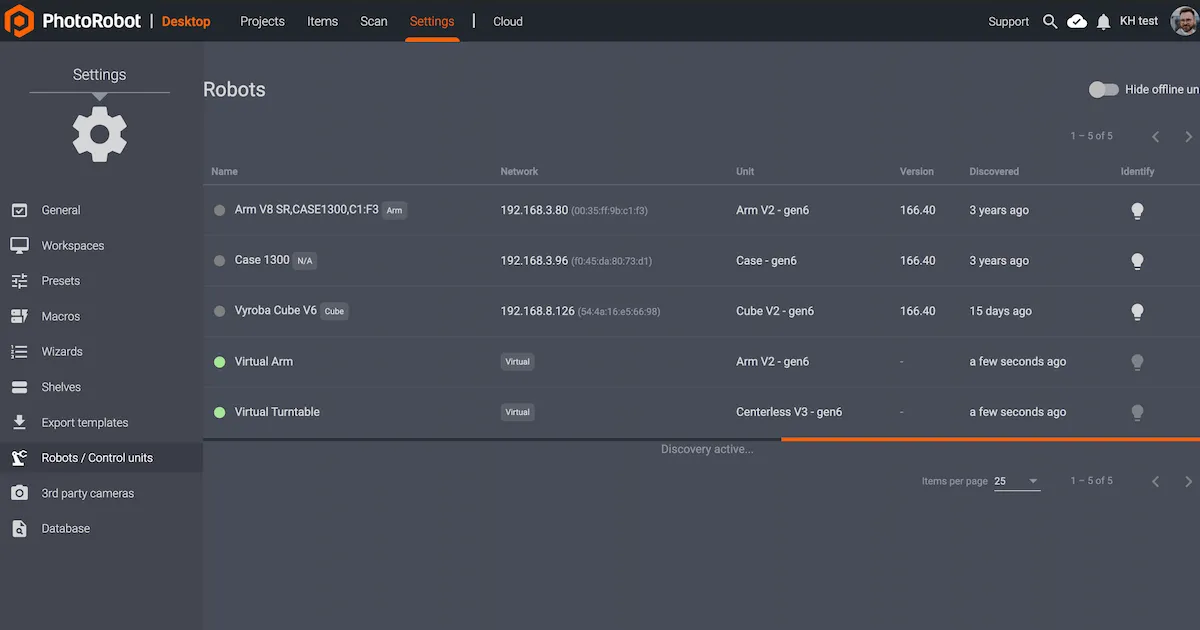
Меню Роботи / Блоки керування відображає стовпці з Назвою, Мережею, Блоком, Версією, Виявлено та Ідентифікувати для кожного робота. Якщо крапка ліворуч від назви робота зелена, він онлайн. Натискання на поле робота відкриє веб-інтерфейс робота. Це також змусить світлодіод на блоці керування робота блимати зеленим для легшої ідентифікації.
3. Детальні вимоги до мережі PhotoRobot
У наведеній нижче інформації докладно описана технічна конфігурація параметрів мережі PhotoRobot. Цей розділ призначений лише для використання досвідченим системним адміністратором у особливих випадках, а також у поєднанні з будь-якими додатковими вказівками та додатковими матеріалами, наданими PhotoRobots спеціально для вашої установки.
Примітка: PhotoRobot – це модульна одиниця, що складається як з апаратного, так і з програмного забезпечення. Що стосується роботи в мережі, то PhotoRobot має два модулі: обладнання PhotoRobot, і маршрутизатор, що підключає PhotoRobot до локальної мережі.
3.1. Загальні вимоги до мережі PhotoRobot
Загальні вимоги до мережі для обладнання PhotoRobot такі.
- У локальній мережі повинен бути DHCP-сервер. Також зазвичай не рекомендується використовувати фіксовану IP-адресу для PhotoRobot. Якщо потрібні фіксовані IP-адреси, зверніться за вказівками до служби підтримки PhotoRobot.
- Локальна підмережа PhotoRobot дозволяє відправляти UDP-трансляції на порти 6666, 67, 53.
- Приймає широкомовну трансляцію UDP на адресу 255.255.255.255, порт 6666.
- Приймає широкомовну трансляцію UDP на свою широкомовну адресу (наприклад, 10.1.2.255), порт 6666.
- Необхідне підключення кабелю Ethernet до локальної мережі місцевого клієнта; Має бути доступний один роз'єм для передачі даних. Уникайте підключення до Wi-Fi.
- Для обладнання PhotoRobot необхідне підключення до інтернету від локальної мережі. В особливих ситуаціях, коли місцеве інтернет-з'єднання недоступне, звертайтеся до служби технічної підтримки.
- Необхідно виконати вимоги наступних розділів щодо блоку керування, необхідних протоколів і портів для роботи локальної мережі, а також хмари PhotoRobot.
3.2. Блок управління (G4, G5)
Блок управління 4 покоління і 5 покоління - це старі версії, які вже застаріли і більше не мають підтримки або обслуговування. У разі виходу пристрою з ладу рекомендується оновлення до новішої версії.
Версії 4 і 5 базуються на RM1 (з високопродуктивним DSC dsPIC33F) або RM32 (з PIC32MX MCU).
- Контролер з RM1 підтримує вбудований інтерфейс 10 Base-T Ethernet з роз'ємом RJ45.
- Контролер з RM2 підтримує вбудований інтерфейс Ethernet 10/100 Base-TX з роз'ємом RJ45.
3.3. Необхідні протоколи та порти для роботи локальної мережі (G4, G5)
Для блоку управління G4 і G5 для роботи в локальній мережі необхідні наступні протоколи і порти.
- Локальна мережа вимагає надсилання трансляцій UDP на порти 6666, 67 і 53.
- Локальні мережі повинні приймати широкомовне мовлення UDP за адресою 255.255.255.255, порт 6666.
- Локальні мережі повинні приймати трансляцію UDP на свою широкомовну адресу (наприклад 10.1.2.255), порт 6666.
- Не потрібно виставляти будь-які з компонентів PhotoRobot безпосередньо в Інтернет через загальнодоступну IP-адресу або NAT.
3.4. Блок управління (G6, G7)
Блок управління G6 і G7 базуються на платформі Beagle Bone Black, яка має процесор ARM Cortex A8 під управлінням кастомізованого дистрибутива Xenomai Linux. Контролер підтримує вбудований Ethernet 10/100, з мережевим інтерфейсом RJ45 для підключення до мережі.
3.5. Необхідні протоколи та порти для роботи локальної мережі (G6, G7)
Для роботи блоку управління G6 і G7 в локальній мережі необхідні наступні протоколи і порти .
- Локальна мережа повинна дозволяти відправляти UDP-трансляції на порти 6666, 67, 53.
- Локальні мережі повинні приймати широкомовне мовлення UDP за адресою 255.255.255.255, порт 6666.
- Локальні мережі повинні приймати трансляцію UDP на свою широкомовну адресу (наприклад 10.1.2.255), порт 6666.
- Не потрібно виставляти будь-які з компонентів PhotoRobot безпосередньо в Інтернет через загальнодоступну IP-адресу або NAT.
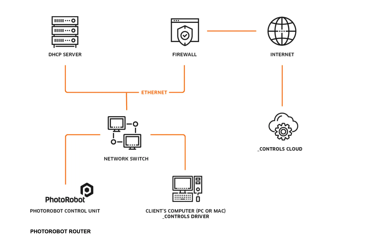
3.6. PhotoRobot Cloud
PhotoRobot Cloud є розширенням локального програмного забезпечення PhotoRobot Controls, і для доступу до хмарних сервісів на PhotoRobot Cloud потрібна активна ліцензія.
Весь зв'язок здійснюється тільки через стандартний захищений порт 443.
Примітка: Для роботи в комп'ютерній мережі потрібні відкриті порти та протоколи, як визначено в системних вимогах PhotoRobot.
4. Підключення PhotoRobot до мережі клієнта
4.1. Перше підключення PhotoRobot до мережі
Для того, щоб вперше підключити обладнання PhotoRobot до мережі замовника, існують такі вимоги:
- PhotoRobot обладнання з блоком управління. Перевірте версію; це має бути G6, G7 або новіше. Блоки управління версій G4 і G5 застаріли і не використовуються для нових установок. Якщо вам потрібно встановити G4 або G5, зверніться до служби технічної підтримки PhotoRobot.
- Комп'ютер клієнта. Це може бути ваш власний ПК / пристрій Windows або MacOS.
- Утиліта тестування для комп'ютера клієнта: frfind.exe для Windows, або frfind для OS X. Завантажте утиліту, відкрийте папку «Завантаження» і двічі натисніть «frfind.tar». Це розпакує виконуваний файл frfind у папці «Завантаження».
- Основна інформація про мережу замовника. Проконсультуйтеся з документацією, якщо вона є, або з IT-адміністраторами вашої компанії.
Щодо основної інформації про мережу клієнта, спробуйте відповісти на наступне:
4а. Чи є одна мережева розетка RJ45 для підключення PhotoRobot?
4б. Чи працює DHCP-сервер під керуванням і розповсюджує IP-адреси, інформацію DNS та інформацію GW?
i. Якщо так, то додаткова конфігурація на PhotoRobot або на комп'ютері клієнта не потрібна.
ii. Якщо сервера DHCP немає, запитайте одну статичну IP-адресу, маску мережі, IP-адресу шлюзу та IP-адресу DNS-сервера.
4.2. Підключення PhotoRobot з блоком управління G5
Якщо підключений блок керування PhotoRobot має версію G5, скористайтеся наведеними нижче інструкціями для підключення PhotoRobot до мережі клієнта.
- Підключіть PhotoRobot за допомогою звичайного кабелю Ethernet до маршрутизатора; кросоверний кабель не потрібен. Очікується, що заводські налаштування залишаться незмінними. Це означає, що не було призначено статичну адресу PhotoRobot, який працює як DHCP-клієнт. Додаткові налаштування мережі не потрібні, якщо в мережі є DHCP-сервер. Якщо потрібна статична адреса, то налаштуйте PhotoRobot на основі кроків для першого підключення до мережі клієнта з попереднього розділу цього документа (4.b.ii).
- Увімкніть обладнання PhotoRobot.
- Підключіть комп'ютер клієнта до того ж роутера, куди підключений PhotoRobot.
- Запустіть тестування утиліти frfind на комп'ютері клієнта, як описано в розділі Базове тестування підключення (5.1.).
- Якщо утиліта тестування frfind виявить PhotoRobot, мережа готова, і ви можете почати виробництво за допомогою програми PhotoRobot Controls.
4.3. Підключення PhotoRobot з блоком управління G6
Якщо блок керування PhotoRobot, що підключається до мережі клієнта, має версію G6, виконайте кроки 1–4 з попереднього розділу (4.2). Потім зверніть увагу:
- Якщо утиліта тестування frfind запускається на комп'ютері клієнта і виявляє PhotoRobot, спробуйте підключити її з комп'ютера клієнта через веб-браузер. Для цього введіть IP-адресу виявленого PhotoRobot в поле адреси браузера, і натисніть enter. Відкриється графічний інтерфейс служби PhotoRobot.
- Якщо графічний інтерфейс служби успішно досягнуто, цей етап тестування завершено, і ви можете почати використовувати виробничу програму PhotoRobot Controls.
4.4. Стандартні мережеві модулі
Стандартними мережевими модулями є:
- Роутер. Маршрутизатор MikroTik встановлює підмережу PhotoRobot всередині мережі клієнта або поруч з нею. Усі пристрої PhotoRobot підключені до локальної мережі маршрутизатора.
- Порти WAN маршрутизатора:
- Останній порт (найбільше число), якщо поставляється маршрутизатор для монтажу в стійку.
- Порт 1, якщо поставляється 4- або 5-портовий маршрутизатор.
- Усі інші порти маршрутизатора налаштовані як порти LAN.
- Адреса підмережі локальної мережі за замовчуванням: 172.31.173.0/24
- IP-адреса локальної мережі маршрутизатора за замовчуванням: 172.31.173.1
- Діапазон DHCP локальної мережі: 172.31.173.10-100
- Порти WAN маршрутизатора:
- Модуль Wi-Fi.
- Модуль Wi-Fi попередньо налаштований на роботу.
- Він працює як точка доступу з SSID PhotoRobotNet, використовуючи пароль: секретний пропуск
5. Діагностика та усунення несправностей
Для діагностики та усунення несправностей мережі PhotoRobot очікується, що PhotoRobot має налаштування за замовчуванням. Це означає, що номери портів не повинні змінюватися, і він діє як клієнт DHCP. Якщо це не так, спочатку скиньте всі зміни до заводських налаштувань.
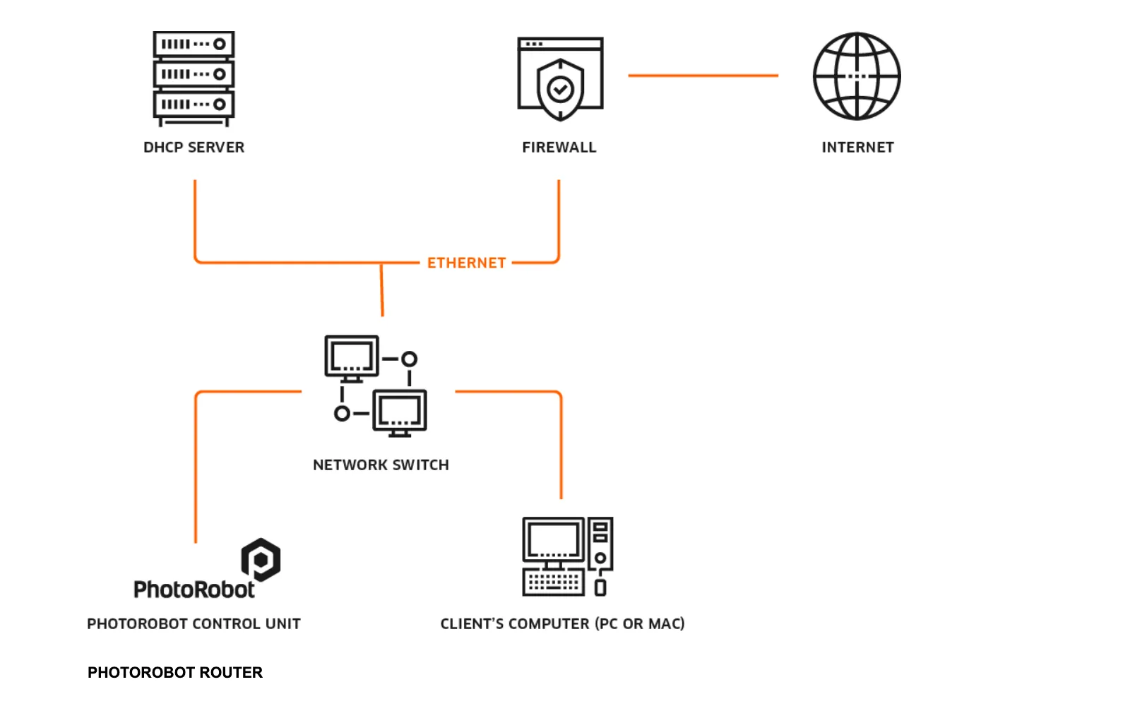
Типова схема з'єднання включає інфраструктуру інтрамережі, представлену комутатором або маршрутизатором, і DHCP-сервер, який видає IP-адреси таким клієнтам, як PhotoRobots, і комп'ютерам клієнтів.
За замовчуванням повинні бути дотримані наступні передумови.
- Існує DHCP-сервер, який розповсюджує IP-адреси, DNS-інформацію та інформацію GW серед клієнтів.
- Є мережевий комутатор з підтримкою портів 10/100 Base-TX, два з яких доступні для PhotoRobot і комп'ютера клієнта. Для підтримки аксесуарів, підключених до мережі, можуть знадобитися додаткові порти, як-от контролер освітлення FOMEI тощо.
- Потрібне структуроване кабельне з'єднання; не використовуйте Wi-Fi.
Попередження: PhotoRobot G6 і комп'ютер під керуванням PhotoRobot повинні бути підключені лише через локальну мережу (Ethernet). Одночасне використання Wi-Fi або кількох мережних адаптерів призведе до проблем із підключенням. Виняток становлять лише флеш-пристрої Broncolor Siros, які підключаються через виділену мережу Wi-Fi, керовану маршрутизатором PhotoRobot (а не Wi-Fi комп'ютера). Виняток становлять лише запити на підтримку для унікальних сценаріїв тестування.
5.1. Базове тестування з'єднання
У разі виникнення проблем рекомендується підключити блок керування PhotoRobot та комп'ютер клієнта відповідно до інфографіки в попередньому розділі «Діагностика та усунення несправностей» (5). Використовуйте утиліту frfind в міру необхідності, щоб виявити всі PhotoRobot в локальній мережі.
Також переконайтеся, що операційна система на комп'ютері клієнта, де буде запущена утиліта, не запущена всередині віртуальної машини (VMware, Parallels і т.д.). Якщо операційна система знаходиться всередині віртуальної машини, утиліта frfind може не отримати доступ до локальної мережі за межами комп'ютера клієнта.
5.2. Вікна
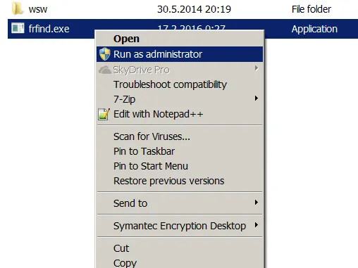
Якщо ОС клієнта - Windows, скачайте утиліту frfind і збережіть завантажений файл frfind.exe в нову локальну директорію, наприклад: C:\TEMP. (Не завантажуйте утиліту на Google Диск, мережевий диск і т.д.).
Далі запустіть frfind.exe з правами адміністратора (або як обмежений користувач).
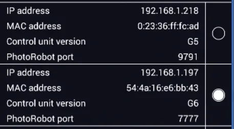
Утиліта Frfind здійснює пошук в локальній мережі по всіх активних інтерфейсах локальної мережі для всіх підключених і запущених PhotoRobots. Якщо деякі з них знайдені, відображаються такі дані:
- IP-адреса.
- MAC-адреса.
- Версія блоку управління.
- Номер порту PhotoRobot.
Потім перевіряється доступність порту PhotoRobot. Зазначимо, що:
- Всі перевірені порти повинні бути відкриті.
- Якщо один або кілька портів закриті, закритий порт виділяється червоним кольором.
- Причиною закритого порту може бути будь-яка проблема з мережею або той факт, що PhotoRobot в даний момент використовується іншою програмою, яка утримує порт.
На наступному зображенні показаний приклад вищезазначеної проблеми в інтерфейсі frfind.
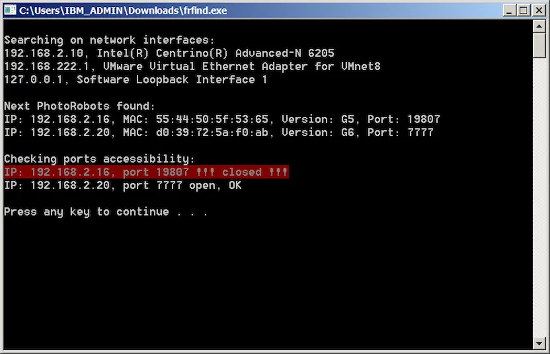
- У наведеному вище випуску виникла проблема з доступом до PhotoRobot 192.168.2.16., оскільки немає доступного порту PhotoRobot. Причина може полягати в проблемі з мережею, або в тому, що хтось в даний момент активно працює з пристроєм, тим самим займаючи порт.
- Додатково зверніть увагу, що IP-адреса мережевого інтерфейсу 192.168.222.1 показує, що цей комп'ютер працює на віртуальній машині. Це може заблокувати підключення PhotoRobot Controls, BASIP або SpinMe від підключення PhotoRobots.
5.3. MacOS
Щоб провести базовий тест підключення на MacOS, завантажте утиліту frfind для Mac OS X. Далі відкрийте папку «Завантаження» у Finder і двічі натисніть «frfind.tar», щоб розпакувати файл frfind у систему Завантаження.
З'явиться командне вікно з пошуком в процесі. Локальна мережа сканується через усі активні інтерфейси локальної мережі на наявність будь-якого запущеного PhotoRobots. Якщо деякі з них виявлено, відображаються їхні IP та MAC адреси, версія та порти:
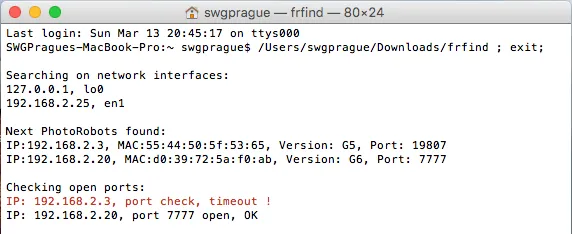
Примітка:
- Всі перевірені порти повинні бути відкриті.
- Якщо порт закритий, він підсвічується червоним кольором.
- Причиною закритого порту можуть бути проблеми з мережею, як-от обмеження брандмауера, або хтось активно працює з пристроєм, таким чином займаючи порт.
5.4. Андроїд
Попередження: з 2025 року додаток для Android більше не підтримується. Його функціональність повністю замінена функціями, інтегрованими в PhotoRobot Controls.
Щоб запустити базовий тест підключення на Android, потрібно завантажити утиліту PhotoRobot (раніше Locator на Google Play) або завантажити через APK. Далі підключіть свій Android-пристрій через WiFi до мережі, де запущено PhotoRobot, і запустіть програму Locator.
Після натискання кнопки «Пошук» в мережі буде виконано пошук PhotoRobot. Якщо буде виявлено PhotoRobot, на наступних екранах локатора відобразяться:
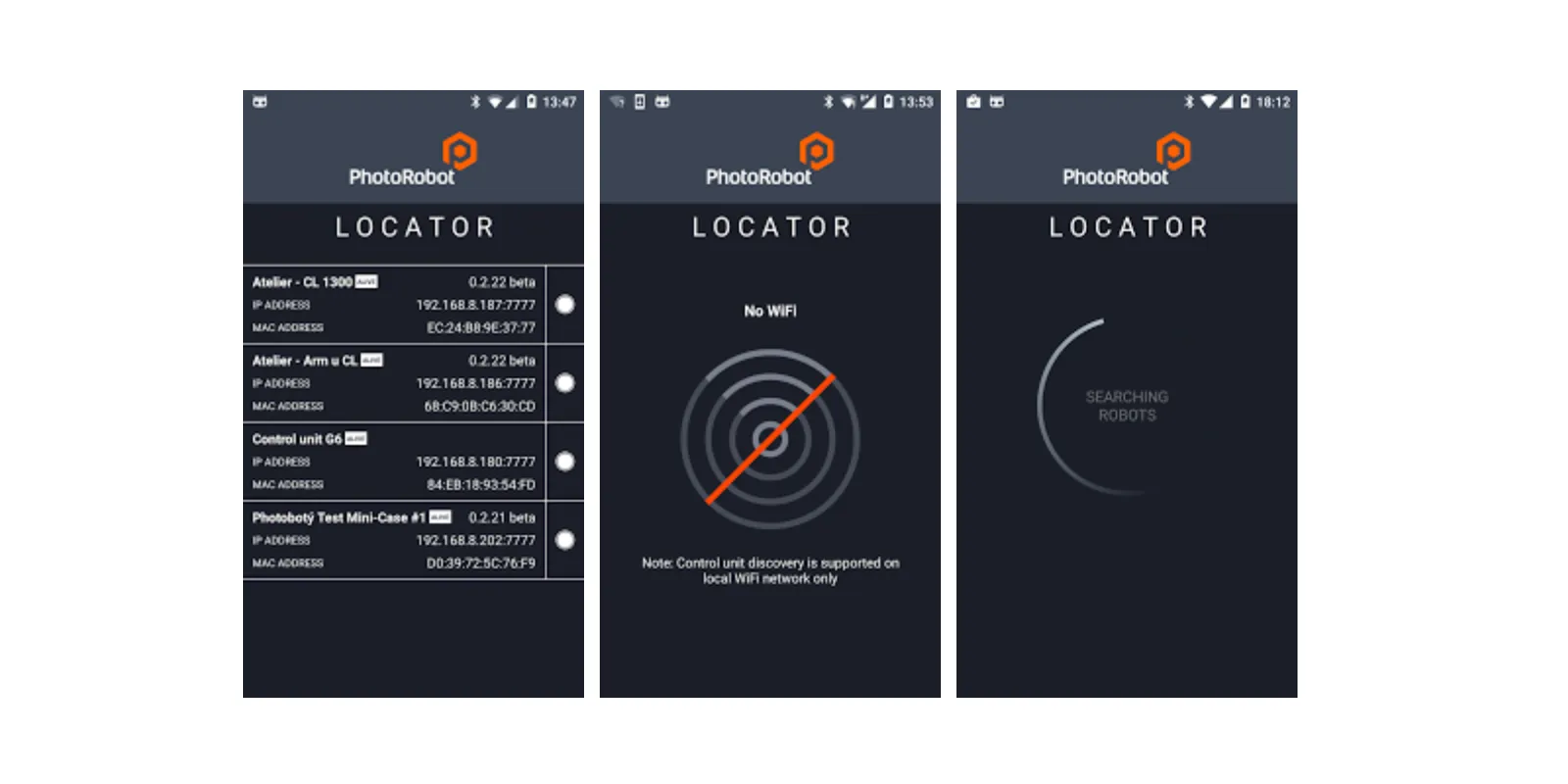
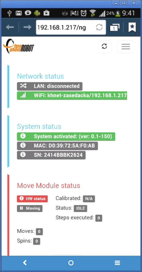
При виявленні блоку управління PhotoRobot G6 запис активний, і доступні дві основні функції.
Перша функція дозволяє натиснути на запис зліва, що відкриває веб-браузер з доступом до графічного інтерфейсу пульта дистанційного керування:
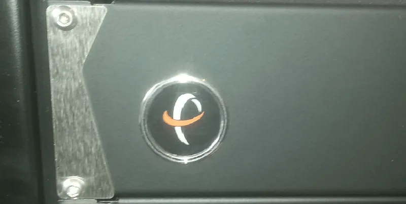
Друга функція допомагає швидко і візуально визначити фізичне місце розташування блоку управління шляхом натискання на коло праворуч від запису. Після цього блок управління буде блимати кнопкою з логотипом PhotoRobot протягом двох секунд.
5.5. Операційна система iOS
Щоб запустити базовий тест підключення на iOS, завантажте утиліту PhotoRobot Locator в App Store. Далі дотримуйтесь тих самих інструкцій, що й для базового тесту підключення Android у попередньому розділі (5.4.).
Примітка: Додаток «Локатор» доступний для iPhone та iPad.
6. Рекомендації
6.1. Активація
Блоки керування PhotoRobot повинні бути активовані для функціональної роботи у виробничому середовищі. Зверніть увагу, що під час процесу активації сервер активації повинен підключитися до Інтернету. Також рекомендується активувати новий PhotoRobot перед транспортуванням до місця розташування клієнта. Для цього потрібно локально підключити систему PhotoRobot до власної мережі з виходом в інтернет, протестувати PhotoRobot та активувати PhotoRobot.
Примітка: Якщо підключення до Інтернету недоступне або обмежене, зверніться до розділу (8) Додатка далі в цьому документі.
7. Відомі проблеми
7.1. PhotoRobot не розпізнається в локальній мережі
Якщо PhotoRobot не розпізнається в локальній мережі, існують такі можливі причини проблеми з такими рішеннями:
- Комп'ютер клієнта блокує зв'язок.
- Спробуйте тимчасово вимкнути брандмауер.
- Спробуйте тимчасово вимкнути будь-яке антивірусне програмне забезпечення.
- Переконайтеся, що утиліта frfind не запущена з віртуальної машини (Parallels, VMware тощо).
- Мережа блокує зв'язок.
- Переконайтеся, що на комп'ютері клієнта не використовується з'єднання через VPN.
- Перевірте, чи правильно підключені комп'ютер клієнта і PhotoRobot до однієї мережі.
- Переконайтеся, що DHCP-сервер правильно розподіляє IP-адреси, інформацію DNS та інформацію GW.
- Перевірте, чи дозволяють мережеві пристрої (комутатор, брандмауер, маршрутизатор) зв'язок на портах, перелічених у цьому документі, характерних для вашої системи.
- PhotoRobot не відповідає.
- Скиньте налаштування PhotoRobot, особливо якщо не потрібно встановлювати статичну IP-адресу.
- Спробуйте підключити PhotoRobot до іншої мережі та перевірте, чи розпізнається така.
7.2. Додаток BASIP не розпізнає PhotoRobot
Увага: З 2015 року програма BASIP більше не підтримується. Його функціональність повністю замінена функціями, інтегрованими в PhotoRobot Controls.
Додаток BASIP в середовищі Windows використовує не всі локальні мережеві інтерфейси для пошуку PhotoRobots. Коли їх більше, BASIP вибирає для роботи тільки один.
Існують такі адаптери для Windows:
- Віртуальний Ethernet-адаптер Vmware для VMnet8
- Локальне підключення адаптера Ethernet
Додатково зверніть увагу на наступні параметри.
- PhotoRobot підключений до тієї ж мережі, що і локальне підключення адаптера Ethernet.
- Програма BASIP шукає PhotoRobots на віртуальному Ethernet-адаптері Vmware для VMnet8.
- BASIP не визнає жодного PhotoRobot.
- Тестова утиліта frfind розпізнає PhotoRobot.
- Рішення полягає в відключенні віртуального ethernet-адаптера VMware для VMnet8 в Windows через налаштування мережевого підключення.
- Кінчик: Запустіть команду «ncpa.cpl» з командного рядка або за допомогою комбінації клавіш WinKey+R для списку мережевих адаптерів і керування ними.
8. Інформація в додатку
8.1. Використання при обмеженому підключенні до Інтернету
В особливих ситуаціях, коли інтернет-з'єднання недоступне в місці встановлення (як правило, військове використання), існують альтернативні методи використання систем PhotoRobot.
Те саме стосується регіонів, де деякі інфраструктури Google обмежені (зазвичай це Китайська Народна Республіка).
Як правило, наступні методи подолання технічних або регуляторних обмежень доступні за запитом за спеціальними умовами та договорами.

Примітка: У таких ситуаціях існує кілька обмежень щодо використання системи.
Будь ласка, зв'яжіться з командою технічної підтримки або вашим інженером з продажу, щоб уточнити деталі та провести тести перед встановленням у вашому середовищі.
8.2. Блоки управління
Що стосується блоків керування (G6 і вище), зверніть увагу, що вони повинні бути активовані ключем активації в автономному режимі (протягом заданого періоду повторення, наприклад: 12 місяців). При цьому початкова та подальші активації виконуються за допомогою унікального рядка активації для віддалених активацій, що надається командою підтримки PhotoRobot в електронному вигляді.
8.3. Пакет хмарних програм PhotoRobot
Зверніть увагу, що пакет хмарного програмного забезпечення PhotoRobot недоступний для використання з обмеженим підключенням до Інтернету. Натомість PhotoRobot _Controls доступний лише у локальній версії.
8.4. Локальний програмний додаток PhotoRobot
PhotoRobot _Controls Додаток має бути активований за допомогою ключа активації в автономному режимі (протягом зазначеного повторного періоду, наприклад: 12 місяців). При цьому перша та наступні активації виконуються за допомогою унікального рядка активації для віддалених активацій, що надається командою підтримки PhotoRobot в електронному вигляді.
8.5. Обліковий запис PhotoRobot
Обліковий запис PhotoRobot (керується в хмарі через веб-інтерфейс) недоступний, коли Google Cloud обмежено. Доступ до хмарного облікового запису можна отримати з необмеженого простору, або клієнт має спеціальну адресу електронної пошти для керування налаштуваннями, виставленням рахунків та іншими проблемами, пов'язаними з обліковим записом.
8.6. Портал підтримки PhotoRobot
Портал підтримки PhotoRobot (керується в хмарі через веб-інтерфейс) недоступний, коли Google Cloud обмежено. Доступ до хмарного облікового запису можна отримати з необмеженого простору, або клієнт має спеціальну адресу електронної пошти для керування заявками на підтримку.


Серія EOS Rebel


Серія цифрових дзеркальних камер EOS


Серія бездзеркальних камер EOS M


Серія PowerShot


Крупним планом / З рук

Серія Canon EOS Rebel пропонує зручні для початківців цифрові дзеркальні камери з надійною якістю зображення, інтуїтивно зрозумілим керуванням і універсальними функціями. Ці камери ідеально підходять для любителів фотографії, забезпечують надійне автофокусування, сенсорні екрани зі змінним кутом нахилу та запис відео у форматі Full HD або 4K.
Підключення
Резолюція (МП)
Резолюція
Цифрові дзеркальні фотокамери Canon EOS забезпечують високу якість зображень, швидке автофокусування та універсальність, що робить їх ідеальними як для фотозйомки, так і для відеозйомки.
Підключення
Резолюція (МП)
Резолюція
Бездзеркальні камери Canon EOS M поєднують у собі компактний дизайн із продуктивністю, як у цифрової дзеркальної фотокамери. Завдяки змінним об'єктивам, швидкому автофокусуванню та високоякісним датчикам зображення ці камери чудово підходять для мандрівників і творців контенту, які шукають портативність без шкоди для якості зображення.
Підключення
Резолюція (МП)
Резолюція
Серія Canon PowerShot пропонує компактні та зручні камери для звичайних фотографів і ентузіастів. Завдяки моделям, починаючи від простих і закінчуючи вдосконаленими камерами зі змінною фокусною відстанню, вони забезпечують зручність, надійну якість зображення та такі функції, як стабілізація зображення та відео 4K.
Підключення
Резолюція (МП)
Резолюція
Камери Canon Close-Up & Handheld призначені для деталізованої зйомки та відеозйомки зблизька. Компактні та прості у використанні, вони забезпечують точне фокусування, зображення з високою роздільною здатністю та універсальні можливості макрозйомки, що ідеально підходить для відеоблогінгу, предметної зйомки та творчих знімків крупним планом.
Підключення
Резолюція (МП)
Резолюція


